
Ripper wiring diagram
 6 Replies
 15385 Views
Recent posts on vintage guitar and bass
 Scan of 1970 Epiphone guitar catalogue produced by Rosetti for the UK market. Undated but most likely from mid-late 1970, this was the first UK catalogue to show the new range of Japanese (Matsumoku) Epiphone guitars. Interestingly, these pages show the Epiphone solid bodies with a single-sided Fender-style headstock layout - a feature quickly replaced with a typical two-sided Epiphone headstock almost immediately. Epiphone electric guitars: 9520, 9525; bass guitars: 9521, 9526; acoustic guitars: 6730, 6830, 6834
 Scan of 1971 Rosetti catalogue (UK) featuring guitars from from numerous manufacturers worldwide: guitars by Epiphone, Hagstrom, Levin, Hoyer, Egmond, Eros, Moridaira, Kiso-Suzuki, Schaller, and Tatra.
 Scan of 1971 Selmer guitar catalogue showing the range of electric and acoustic guitars distributed by the company: guitars by Gibson, Yamaha, Selmer, Hofner and Suzuki. 1960s Selmer had always placed Hofner at the front end of their catalogues, no doubt these were the better sellers - but into the 1970s Hofner were slipping somewhat and only appear at the tail end of this publication, pride of place going to Gibson, and to a lesser extent Yamaha. In fact this is the last Selmer catalogue to include the many Hofner hollow bodies (Committee, President, Senator etc) that had defined the companies output for so many years - to be replaced in the 1972 catalogue by generic solid body 'copies' of Gibson and Fender models. A number of new Gibson models are included for the first time: the SG-100 and SG-200 six string guitars and the SB-300 and SB-400 basses.
 Scan of 1968/1969 Selmer guitar catalogue (printed July 1968), showing the entire range of electric and acoustic guitars distributed by the company: guitars by Hofner, Gibson, Selmer and Giannini. Selmer were the exclusive United Kingdom distributors of Hofner and Gibson at the time, and this catalogue contains a total of 18 electric guitars, 7 bass guitars, 37 acoustics, and 2 Hawaiian guitars - all produced outside the UK and imported by Selmer, with UK prices included in guineas. This catalogue saw the (re-)introduction of the late sixties Gibson Les Paul Custom and Les Paul Standard (see page 69) and the short-lived Hofner Club 70. Other electric models include: HOFNER ELECTRICS: Committee, Verithin 66, Ambassador, President, Senator, Galaxie, HOFNER BASSES: Violin bass, Verithin bass, Senator bass, Professional bass GIBSON ELECTRICS: Barney Kessel, ES-330TD, ES-335TD, ES-345TD, ES-175D, ES-125CD, SG Standard, SG Junior, SG Special GIBSON BASSES: EB-0, EB-2, EB-3 - plus a LOT of acoustics branded Gibson, Hofner, Selmer and Giannini
 Hofner Colorama was the name UK distributor Selmer gave to a series of solid and semi-solid guitars built by Hofner for distribution in the UK. The construction and specifications of the guitars varied over the period of production, but by 1961 it was a totally solid, double cutaway instrument, with a set neck, translucent cherry finish, six-in-a-row headstock, and Hofner Diamond logo pickups. Available as a single or dual pickup guitar, this sngle pickup version would have been sold in mainland Europe as the Hofner 161.
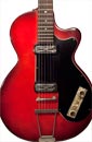
 Commodore was a brand applied to a series of guitars produced in Japan at the well-respected Matsumoku plant from the late 1960s to the mid 1970s - and sold primarily (perhaps exclusively?) in the United Kingdom. The models bearing the Commodore name were all guitars available from different distributors with different branding. Although there may have been some minor changes in appointments (specifically headstock branding) most had the same basic bodies, hardware and construction. Equivalent models to the Commodore N25 (and this is by no means an exhaustive list) include the Aria 5102T, Conrad 5102T(?), Electra 2221, Lyle 5102T, Ventura V-1001, Univox Coily - and most famously the Epiphone 5102T / Epiphone EA-250.
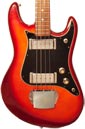
 The Hofner Colorama was the name given by Selmer to a series of solid (and semi-solid) body Hofner guitars distributed in the United Kingdom between 1958 and 1965. The Colorama name actually applied to some quite different guitars over the period, but in 1960 it was a very light, semi-solid, set necked guitar with one (Colorama I) or two (Colorama II, as seen here) Toaster pickups. Although an entry-level guitar, it was very well-built, and a fine playing guitar; certainly a step up (at least in terms of craftsmanship) from many of the Colorama guitars that would follow, and a good deal of the guitars available in Britain circa 1960.
 By the end of the 1960s, a decision had been made to move Epiphone guitar production from the USA (at the Kalamazoo plant where Gibson guitars were made), to Matsumoto in Japan, creating a line of guitars and basses significantly less expensive than the USA-built models (actually less than half the price). The Matsumoku factory had been producing guitars for export for some time, but the 1820 bass (alongside a number of guitar models and the 5120 electric acoustic bass) were the first Epiphone models to be made there. These new Epiphones were based on existing Matsumoku guitars, sharing body shapes, and hardware, but the Epiphone line was somewhat upgraded, with inlaid logos and a 2x2 peghead configuration. Over the course of the 70s, the Japanese output improved dramatically, and in many ways these early 70s models are a low point for the brand. Having said this, there are a lot worse guitars out there, and as well as being historically important, the 1820 bass can certainly provide the goods when required.
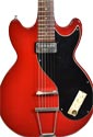
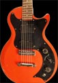 Production of Bill Lawrence's Gibson Marauder began in 1974, with production peaking in 1978. But by 1980 the model was officially discontinued, though very small numbers slipped out as late as spring 1981. Over 7000 examples shipped between 1974 and 1979, and although no totals are available for 1980 and 1981, it is unlikely production reached three figures in either of these years. These final Marauders were all assembled at the Gibson Nashville plant, and had some nice features not available through the later years of production, such as a rosewood fretboard, and in this case, an opaque 'Devil Red' finish. It's a great looking and fine playing guitar!